
A Beginner’s Guide to Designing Arrays for Laser Cutting
Time : May 07, 2026 View : 679
People who have dedicated numerous hours to the manual duplication and placement of a basic washer or a compact gear onto a computer interface can appreciate the exhausting quality of such recurring efforts. Developing an array serves as the key method to transition from an amateur approach to a structured manufacturing procedure. This technique extends beyond mere replication. Instead, it focuses on populating a panel of metal or acrylic through the most intelligent arrangement feasible. Consequently, expenses related to unused remnants become minimized. For those seeking superior machinery capable of managing substantial production volumes, an examination of Wisecut is advisable, as it integrates manufacturing accuracy with accessible operational features.
Why Do Arrays Matter in Laser Cutting?
Operators managing a commercial enterprise or an occupied facility recognize that time constitutes the predominant expenditure. Arrays facilitate the expansion of a single impeccable sketch throughout the operational area in mere moments. As a result, uniformity ensures that each element produces an exact duplicate. Furthermore, this system assists in determining the precise quantity of components that can occupy a conventional 4×8 panel. Utilizing organized grid formations maintains the laser mechanism along a reliable trajectory. Such consistency diminishes mechanical degradation over extended use. In addition, it streamlines the process of providing cost estimates to clients, given the clear understanding of material utilization rates.
Designing Your Base Component
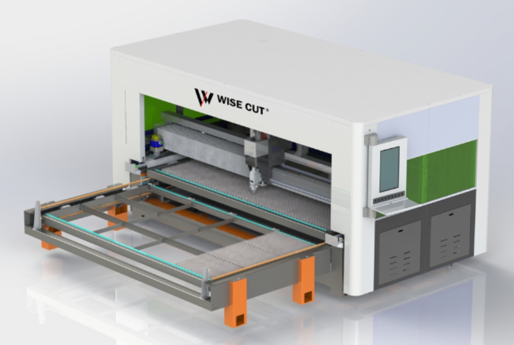
Prior to engaging the array function, the foundational form requires absolute perfection. Consider this element as the core blueprint for the full manufacturing sequence. Should a minor discontinuity appear in any line or an unintended duplicate route exist within the primary item, such imperfections will proliferate extensively across the entire surface. Establish all measurements with meticulous care. For example, when preparing to fabricate a 50mm disc, confirm that the size aligns exactly without any fractional discrepancies like 50.05mm. Moreover, incorporating modest tabs or micro-joints into the original design proves beneficial if concerns persist regarding diminutive elements slipping past the supports on the fabrication platform. In scenarios demanding robust industrial performance, numerous experts depend upon an Exchange Table Fiber Laser Laser Cutting Machine to sustain operational continuity while arranging the subsequent panel of essential structures.
How to Determine Your Array Parameters?
Calculations enter the process here, though they need not intimidate participants. It becomes necessary to establish the offset, essentially the interval separating individual components. When elements position too closely, the generated thermal energy from the laser risks deforming the slender residue of substance that remains. A reliable guideline recommends sustaining the interval at a minimum matching the depth of the substance under fabrication. Additionally, incorporation of the kerf becomes essential, representing the precise breadth of the laser’s focal point. Neglecting this factor may yield components diminished by mere fractions of a millimeter. Therefore, outline the arrangement of rows and columns in accordance with the complete dimensions of the equipment’s platform. Discovering that the overall array surpasses the effective fabrication zone by even 10mm often leads to regrettable adjustments.
Using Array Functions Effectively?
The majority of drafting applications, encompassing both general CAD systems and specialized laser programs, incorporate a focused array mechanism. Selection of a Linear Array suits straightforward rectangular arrangements, whereas a Polar Array accommodates circular distributions, such as the positioning of edges on an expansive cutting tool. Certain progressive solutions include nesting functionalities. Nesting resembles a strategic arrangement puzzle in which the application pivots and nestles forms together to conserve additional resources. In cases where nesting remains unavailable, reliance on a tidy grid formation suffices. This option accelerates the subsequent removal of debris and the gathering of completed items for the operational group.
How to Refine Your Layout for Efficiency?
Upon displaying the grid within the visual interface, a momentary pause allows evaluation of the unoccupied regions. An extra row might integrate seamlessly following a subtle 5mm repositioning of the assembly. This juncture involves scrutinizing the trajectory of the cutting operation. Should the laser necessitate relocation from the lower left extremity to the upper right following each form, considerable durations accumulate in unproductive transit periods. Efforts to maintain a continuous sequence in the trajectory prove advantageous. Consideration of common line cutting also merits attention. This established practice enables contiguous components to utilize a unified incision path. Such an approach benefits geometric forms like squares and rectangles by substantially halving the required processing duration, albeit demanding precise configuration to avert thermal damage at juncture points.
Practical Tips and Final Checks
Transmission of the file to the apparatus should follow a preliminary simulation or perimeter verification. This procedure delineates the precise course the laser will follow absent actual activation of the energy source. Verification of lead-ins and lead-outs remains crucial. These designated entry locations facilitate initial penetration into the substance. Positioning them along vital boundaries of a component risks introducing minor indentations. Routine consultation of the news center provides essential insights into contemporary configurations for substances and expedited techniques within the software. As a concluding step, confirmation of the material’s evenness ensures optimal results. A configuration comprising 200 units achieves viability solely through unwavering laser concentration, since any curvature in the substrate will compromise the concluding segments of the production cycle.
Should difficulties emerge or guidance be required regarding apparatus selection aligned with distinct substance requirements, professional support is accessible through contact us.
FAQ
Q1: What is the difference between a grid array and nesting?
A: A grid array duplicates forms within linear rows and columns, whereas nesting manipulates and integrates shapes to accommodate the maximum quantity within non-uniform zones.
Q2: Can I use arrays for different shapes on the same sheet?
A: Yes, assembly of varied component groupings permits subsequent application of an array to the collective unit, thereby optimizing surface utilization.
Q3: Why did my laser stop halfway through an array?
A: Interruptions of this nature generally arise when the document volume overwhelms the apparatus controller or when array confines surpass the tangible boundaries of the mechanism’s mobility.
Q4: How much space should I leave between parts?
A: Allocation of an interval equivalent to at least the substance’s thickness generally suffices to mitigate thermal distortion and uphold the durability of the residual panel.
Q5: Is common line cutting recommended for beginners?
A: Initiation with conventional intervals is preferable. Common line cutting necessitates highly accurate energy calibrations to prevent excessive scorching along the mutual boundary subjected to dual laser traversals.


