

Metal Fabrication Automation Solutions: A Guide to Cutting, Bending and Welding
Time : Oct 30, 2026 View : 100
Metal fabrication automation solutions are no longer limited to a robot placed beside one machine. Modern shops can connect laser cutting, sheet handling, CNC bending, welding, inspection, and production data into a coordinated workflow. The practical question is where automation will remove a real constraint in the factory.
A cutting system may be fast while parts wait for sorting. A press brake may have adequate capacity while operators spend most of the shift lifting and rotating blanks. A welding robot may repeat a seam accurately while manual fit-up creates variation before the weld starts. A useful automation plan looks at the complete route from raw material to qualified assembly.
This guide explains automation levels for cutting, bending, and welding, then shows how to select equipment, measure results, and build a phased implementation plan.
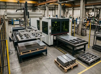
What Are Metal Fabrication Automation Solutions?
Metal fabrication automation can be divided into three practical levels. Machine-level automation adds functions such as automatic loading, unloading, probing, tool changing, or program selection to one machine. A robotic cell connects a machine with a robot, gripper, positioner, or inspection device. An integrated line links several processes with material buffers, software, and traceability.
The right level depends on product volume, part variety, material size, labor availability, and process stability. A job shop with constantly changing drawings may benefit from automated loading and digital programming while keeping final handling manual. A manufacturer producing the same cabinet family every day may justify a connected cutting, bending, and welding flow.
Automation should be designed around a defined part family. If drawings, bend sequences, weld joints, or material specifications change every week, the project needs flexibility before it needs maximum integration.
Automating Laser Cutting
Automated Loading and Unloading
Laser cutting automation often starts with material handling. A storage tower, shuttle table, or loader places raw sheets on the cutting bed. After cutting, a sorter separates nested parts, skeletons, and scrap. Finished blanks can be stacked by job, material, or downstream process.
This arrangement reduces waiting between sheets and limits manual lifting. It also creates a more predictable handoff to bending. The equipment must be matched to maximum sheet length, width, thickness, weight, surface condition, and storage capacity. A loader that cannot handle the heaviest common blank will still leave a manual bottleneck.
CNC Laser Cutting and Process Data
The cutting program should connect the CAD drawing, nesting layout, material database, nozzle selection, assist-gas settings, and inspection information. Correct nesting can improve material yield, but it must also consider how parts will be separated and identified after cutting.
Cut-edge quality affects later operations. Excessive dross, heat distortion, or incorrect pierce settings can create problems during bending and welding. For a complete equipment review, compare fiber laser cutting machine options with the materials and part sizes used in your factory.
Automating CNC Bending
Robotic Press Brake Cells
A robotic press brake cell uses a robot or dedicated manipulator to load blanks, position them against the back gauge, rotate them, and stack completed parts. The press brake controls ram movement, bend sequence, and back-gauge positions, while the robot manages repeated handling.
This setup is useful for parts with a stable geometry and a repeatable bend sequence. It can reduce operator lifting and maintain production during long batches. Gripper design is important: the robot must handle different blank sizes, protect finished surfaces, and maintain a reliable grip near the bend line.
Panel Bending and Bending Centers
A panel bender or CNC bending center clamps the blank and uses forming blades to create flanges. The sheet can remain under control through several bends, with programmed repositioning or rotation. This makes the technology attractive for cabinets, enclosures, panels, and short-flange products.
The process is less suitable as a universal replacement for a press brake. Heavy plate, extra-long parts, unusual shapes, and very small batches may still be easier to produce on a conventional punch-and-die machine. Automation should follow the geometry and volume of the actual order book.
When Manual Handling Still Makes Sense
Manual loading can be sensible for prototypes, repair parts, and high-mix work. A flexible CNC press brake may allow a skilled operator to change tools and bend sequences quickly. A phased project can automate material loading first, then add robotic handling after the part family and process data are stable.
Automating Welding After Cutting and Bending
Robotic MIG, TIG, and Laser Welding
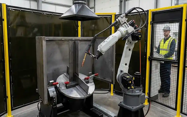
Welding automation ranges from powered positioners and seam tractors to fully robotic cells. MIG robots are common for repeat structural joints. TIG automation can suit controlled, appearance-sensitive seams. Laser welding can support precise, low-distortion joints when the material, fit-up, and safety enclosure meet process requirements.
The selection should consider joint design, material type, thickness, required penetration, weld length, appearance, and production volume. A robot cannot compensate for an inconsistent joint gap or poorly prepared edge.
Fixtures, Positioners, and Seam Tracking
Fixtures establish the relationship between the parts, torch, and robot. They must locate components repeatedly without blocking the weld path. Positioners rotate the assembly so the robot can maintain a productive torch angle and travel direction.
Seam tracking, touch sensing, laser vision, and offline simulation can help manage variation. These systems add cost and require calibration, so they should be specified according to the tolerance of the product. Stable fit-up often provides a better first investment than advanced sensing alone.
Welding Safety and Fume Control
An automated welding cell needs guarding, door interlocks, emergency stops, light or laser protection where applicable, fume extraction, and clear operator procedures. Safety controls must cover loading, maintenance, teaching, and recovery after a fault. Training remains essential even when the robot performs the torch movement.
How Cutting, Bending, and Welding Work as One System
CAD/CAM → Laser Cutting → Sorting → Bending → Fit-Up → Welding → Inspection
Each handoff must preserve part identity and process information. Barcodes, QR codes, or a manufacturing execution system can connect the flat pattern, bending program, weld recipe, inspection result, and shipment record.
Buffer design is equally important. If the laser cuts faster than the bending cell can process, parts need a controlled queue. If welding is slower, finished bent components may fill the floor and hide the real constraint. Line balancing should use measured cycle times, changeover time, operator touch time, and planned downtime.
Sorting is often overlooked. A perfectly cut part placed in the wrong job becomes a bending or welding problem later. Automated identification and job-based stacking can prevent this error without requiring a fully lights-out factory.
Choosing the Right Automation Level
Level 1: Machine-Level Automation
Start with automatic laser loading, sheet storage, CNC program management, press brake back-gauge control, or a welding positioner. These upgrades can improve flow without changing the complete factory layout.
Level 2: Robotic Cells
Robotic bending and welding cells reduce repetitive handling and create repeatable cycles. They require dependable fixtures, grippers, safety systems, and programs. A cell should be tested with representative parts before the purchase is finalized.
Level 3: Integrated Production Lines
An integrated line links cutting, sorting, bending, welding, and logistics. This level suits stable product families, regular demand, and factories prepared to manage software, maintenance, and process qualification. It can deliver a smooth material flow, but it also creates a larger shared dependency if one station stops.
What Parts and Production Profiles Benefit Most?
Automation usually produces the clearest value for electrical enclosures, machine housings, HVAC panels, cabinets, shelves, and welded assemblies with repeatable designs. These products have known material specifications, repeat bend sequences, and predictable weld locations.
High-mix, low-volume work needs a different approach. Flexible programming, quick-change tooling, offline preparation, and modular automation may be more useful than a fixed line. Large or heavy workpieces may also need cranes, custom fixtures, or manual intervention for safe handling.
Before automating, confirm that drawings, tolerances, bend allowances, weld symbols, and inspection criteria are controlled. Process stability is a prerequisite for reliable automation.
How to Measure Productivity, Quality, and Labor Savings
Measure the complete process rather than one machine specification. Useful indicators include:
Overall cycle time from blank to finished assembly
Setup and changeover time
Material handling time
First-pass yield
Scrap and rework
Operator touch time
Equipment utilization
Unplanned downtime
Automation may move a bottleneck instead of removing it. Faster cutting can increase sorting work. Faster bending can create a queue before welding. A successful project measures every stage before and after installation.
Cost, Integration, and Maintenance Considerations
The investment can include laser equipment, bending machinery, welding robots, fixtures, grippers, storage, conveyors, safety systems, software, installation, training, and spare parts. Utility requirements also matter. Laser sources, compressors, assist gases, extraction, and welding power supplies affect operating cost.
Maintenance planning should identify critical components, inspection intervals, backup procedures, and expected spare-part lead times. Remote diagnostics can reduce troubleshooting time, while local technical support may be important for recovery after a mechanical or software fault. Review the supplier’s metal fabrication equipment service support before approving an integrated project.
Practical Implementation Roadmap
1. Collect order, material, cycle-time, and quality data.
2. Select a repeatable part family with a visible constraint.
3. Map cutting, sorting, bending, fit-up, welding, and inspection.
4. Confirm blank size, weight, thickness, tolerances, and joint design.
5. Start with one machine upgrade or robotic cell.
6. Test programs, fixtures, grippers, and safety functions.
7. Define acceptance criteria using real production parts.
8. Train operators and maintenance staff.
9. Review utilization, yield, labor, and downtime after launch.
10. Expand to connected processes only when the data supports it.
WiseCut Metal Fabrication Automation Solutions
WiseCut provides laser cutting, welding, and CNC bending equipment for industrial metal fabrication. Machine selection can be based on material, thickness, workpiece size, production volume, control requirements, and available factory space. Product materials include hydraulic CNC press brake configurations with DELEM controllers, servo back gauges, segmented tooling, and compensation systems. These machine-level specifications should be matched to the wider automation plan rather than treated as whole-line performance. For a project review, request a customized fabrication automation plan with drawings, material data, expected volume, and the desired automation level.
FAQ
Q1: What are metal fabrication automation solutions?
A: They are equipment, robotics, software, and handling systems that automate one or more fabrication steps, including laser cutting, bending, welding, inspection, and material movement.
Q2: Can laser cutting, bending, and welding be automated in one line?
A: Yes, when the part family, process data, fixtures, buffers, and quality requirements are stable. Many factories begin with individual cells before connecting the full route.
Q3: Which metal fabrication process should be automated first?
A: Start with the operation that creates the largest measurable constraint, such as repetitive loading, sorting, bending handling, or welding labor. Use production data to identify it.
Q4: Is automation suitable for low-volume custom fabrication?
A: Modular automation can help, especially for loading, programming, and positioning. A fixed integrated line may be difficult to justify when parts and processes change constantly.
Q5: What information is needed for an automation proposal?
A: Provide drawings, materials, thicknesses, part sizes, weights, monthly volume, bend and weld requirements, quality tolerances, current cycle times, and available floor space.


