

Fiber Laser Cutting Speed Chart for Carbon Steel, Stainless Steel, and Aluminum
Time : Sep 18, 2026 Vista : 41
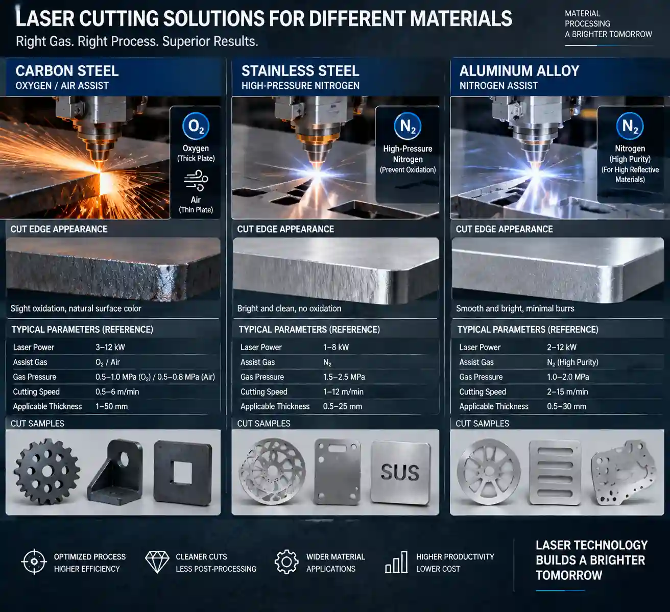
A fiber laser cutting speed chart gives you a starting feed rate for a material and thickness. It does not provide a universal production setting. Laser power, material grade, sheet tolerance, assist gas, nozzle, focus position, cutting head, and edge-quality target all change the result. Use the ranges below for planning, then validate them on the actual machine with a test coupon.
How to Read a Fiber Laser Cutting Speed Chart?
Cutting speed is the feed rate while the beam is melting and ejecting material. It is different from a machine’s maximum no-load or positioning speed. Pierce time, acceleration, corner control, and part geometry also affect completed-part output.
Charts usually group data by laser power and thickness. Thin sheet can run at a high feed rate, while thicker plate needs more energy per millimetre and a slower feed. The same nominal thickness can cut differently when the grade, surface condition, or reflectivity changes.
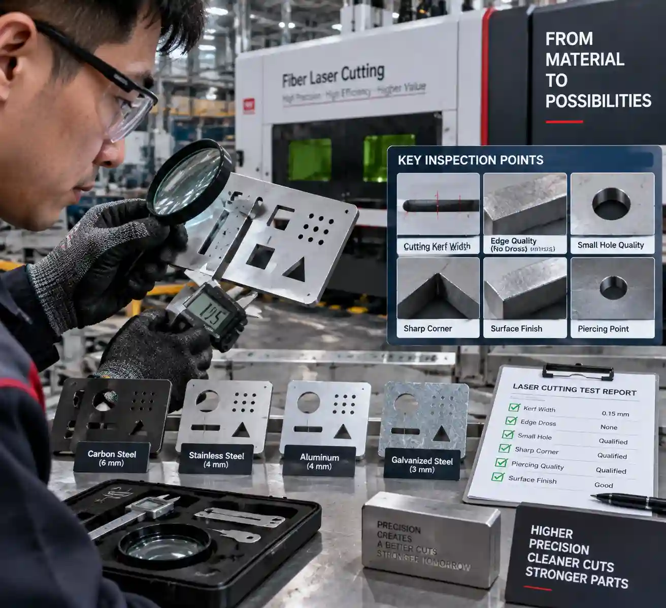
Treat a published chart as a process window. Start near the middle of the suggested range, cut a short test line or coupon, and inspect penetration, dross, kerf width, and heat tint before releasing a production program.
Reference Speed Chart for Carbon Steel, Stainless Steel, and Aluminum
The table is a general planning reference for flat-sheet fiber laser work. Values are broad starting ranges; production results require machine testing. They assume a clean sheet, a correctly aligned cutting head, suitable gas supply, and a quality target appropriate for ordinary fabrication. Confirm the recipe with your machine supplier.
|
Material and assist gas |
Thickness |
Typical power class |
Starting speed range* |
|
Carbon steel, oxygen or air |
1–3 mm |
1.5–3 kW |
3,000–10,000 mm/min |
|
Carbon steel, oxygen |
4–8 mm |
3–6 kW |
1,200–4,500 mm/min |
|
Carbon steel, oxygen |
10–16 mm |
6–12 kW |
500–1,800 mm/min |
|
Stainless steel, nitrogen |
1–3 mm |
1.5–3 kW |
2,500–8,000 mm/min |
|
Stainless steel, nitrogen |
4–8 mm |
3–6 kW |
900–3,500 mm/min |
|
Stainless steel, nitrogen |
10–16 mm |
6–12 kW |
300–1,400 mm/min |
|
Aluminum, nitrogen or air |
1–3 mm |
1.5–3 kW |
3,000–9,000 mm/min |
|
Aluminum, nitrogen or air |
4–8 mm |
3–6 kW |
1,000–4,000 mm/min |
|
Aluminum, nitrogen or air |
10–16 mm |
6–12 kW |
300–1,500 mm/min |
*Planning ranges only. Actual speed depends on alloy, reflectivity, laser source, nozzle diameter, focus, gas pressure and purity, pierce strategy, and required edge quality. A 20 kW system can process thicker material, but higher power does not make every thin-sheet job proportionally faster.
For carbon steel, oxygen adds an exothermic reaction that supports penetration and can reduce gas cost. Nitrogen or air may be selected when surface oxidation matters. Stainless steel generally uses nitrogen to protect the edge from oxidation. Aluminum reflects more energy and conducts heat quickly, so focus, nozzle condition, and piercing stability deserve close attention.
Laser Cutting Parameters That Change Real-World Speed
Laser Power and Material Thickness
Power sets the available energy, while thickness determines how much material must be heated and expelled. Raising power can widen the usable speed window, especially on medium and thick plate. Correct focus and gas flow remain required. Select a power class from the thickness you cut every day and the full thickness mix. A single maximum-thickness requirement is an incomplete basis for selection.
Assist Gas, Nozzle, and Focus
Assist gas removes molten metal from the kerf. Gas type, pressure, purity, and nozzle diameter influence cut stability. A partially blocked nozzle can produce dross even when the programmed speed is reasonable. Focus position changes energy density through the sheet; use the cutting head maker’s process window as the starting reference and record each adjustment.
Edge Quality, Dross, and Heat Input
Speed is a quality decision as well as a throughput setting. If the feed rate is too high, the beam may leave uncut bridges, heavy bottom dross, or a rough edge. If it is too low, heat input can widen the kerf, increase discoloration, and damage small features. Corners and short contours need their own acceleration and power behavior, so a straight-line test does not represent every part.
When a chart value produces unstable results, change one variable at a time. Confirm the sheet grade and thickness, inspect the protective window and nozzle, check gas delivery, then adjust speed in small steps. Record the setting with the material heat, gas, nozzle, focus, and quality result.
How to Tune Cutting Speed on the Shop Floor?
- Identify the exact material grade, thickness, surface coating, and sheet batch. 2. Confirm the laser power, cutting head, nozzle type, nozzle diameter, and focus reference. 3. Set the recommended assist gas and verify pressure at the machine and at the regulator. 4. Cut a test coupon containing a straight line, a small hole, and a corner. 5. Inspect top and bottom edges for penetration, dross, striations, burrs, and heat tint. 6. Adjust speed or power in a small step, then repeat the same coupon. 7. Save the approved recipe with date, material, thickness, gas, nozzle, focus, and operator notes.
This record reflects your source, optics, maintenance condition, and quality target. When production thickness is close to the machine’s limit, ask for a supplier test cut and compare it with the brochure number.
Choosing a Fiber Laser for Your Thickness Mix
Build a thickness histogram from your last few months of work. Note the percentage of thin sheet, medium plate, and occasional heavy jobs, then compare the speed at those daily thicknesses. Also check bed size, loading method, duty cycle, gas availability, extraction, and the controller’s ability to manage piercing and height following.
WiseCut’s official product page lists the WT-12025 high-power full-cover fiber laser cutting machine with a 6,000–30,000 W laser-power range, FSCUT8000E control system, and BOCI BLT662 auto-focus head. The page lists 120 m/min as maximum no-load running speed, a positioning specification that differs from material cutting speed. It also describes applications for stainless steel, carbon steel, alloy steel, aluminum alloys, galvanized sheet, aluminized-zinc sheet, other metal plate, and steel pipes.
The same page gives different maximum-thickness statements in its description and specification field. Treat those figures as model- and test-condition-specific items to confirm in writing. For product options and machine scope, review the máquinas de corte por láser de fibra category and the high-power full-cover fiber laser cutting machine page.
Conclusion: Turn a Chart Into a Verified Cutting Recipe
A fiber laser cutting speed chart helps you estimate a power class and a first test setting. The production recipe comes from controlled trials that match your material, gas, nozzle, focus, geometry, and edge standard. Keep cutting speed separate from no-load machine speed and maximum thickness.
WISECUT BEIJING WISECUT LTD publishes fiber laser cutting machines with configurable power classes and documented control and cutting-head options. When you compare a machine, send the supplier your material grades, daily thickness mix, sheet size, gas preference, edge-quality target, and sample files. The WiseCut contact team can then confirm an appropriate configuration and identify which speed and thickness claims require a test cut.
Preguntas frecuentes
P1: What is the best cutting speed for carbon steel on a fiber laser?
R: There is no single best value. Start with the chart range for your thickness and power, then tune oxygen or air flow, focus, and speed against penetration and dross on the actual sheet.
P2: Why does stainless steel need different laser cutting parameters?
R: Stainless steel usually uses nitrogen to limit oxidation and protect edge appearance. Its alloy, thickness, gas purity, nozzle, and focus change the usable speed window, so a carbon-steel recipe should not be copied directly.
P3: Can the same fiber laser speed chart be used for aluminum?
R: Use aluminum-specific rows as a starting point. Reflectivity and high thermal conductivity affect piercing and heat removal, so validate nozzle alignment, focus, gas and speed with a coupon.
P4: Does a machine’s 120 m/min running speed equal cutting speed?
R: No. A listed 120 m/min no-load speed describes head movement during positioning. Material cutting speed is lower and depends on thickness, power, gas, geometry, and edge-quality requirements.
P5: How do you verify a speed-chart value before production?
R: Cut a repeatable coupon using the exact material and thickness, inspect penetration and edge condition, adjust one parameter at a time, and save the approved recipe with its gas, nozzle, focus, and date.


